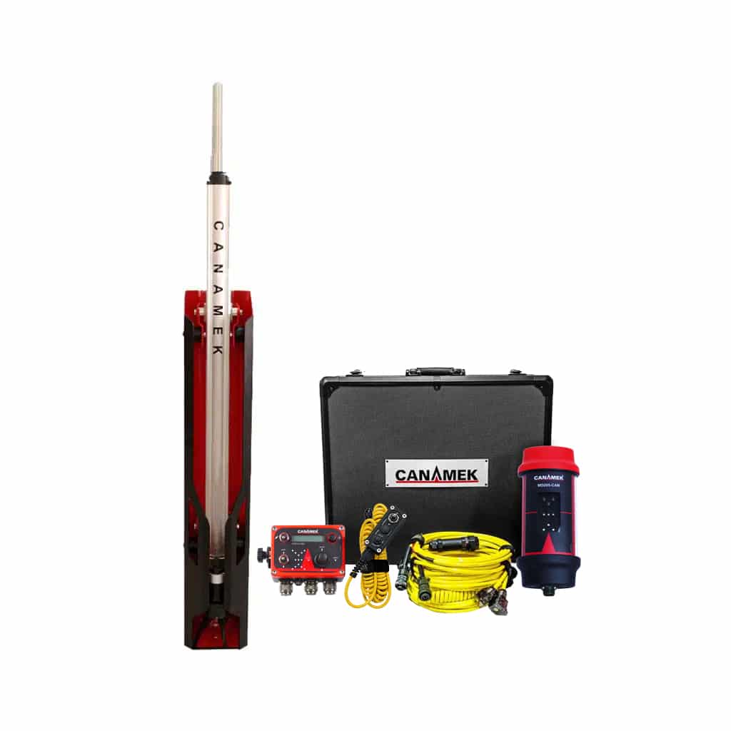
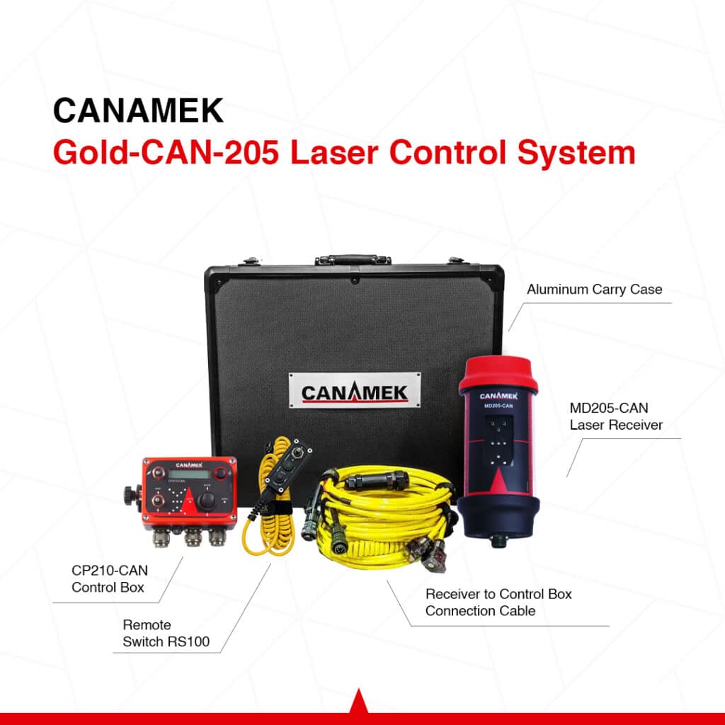
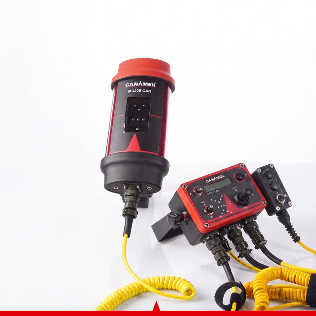
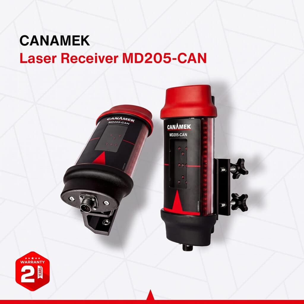
The CANAMEK-Gold-CAN Laser Land Leveling Control System with Power Mast is a laser land leveling system with power mast adjustment built into the package. It combines the CP210-CAN control box, MD205-CAN laser receiver and PM400-CAN electric mast for grade guidance, automatic blade control and relative elevation surveying.
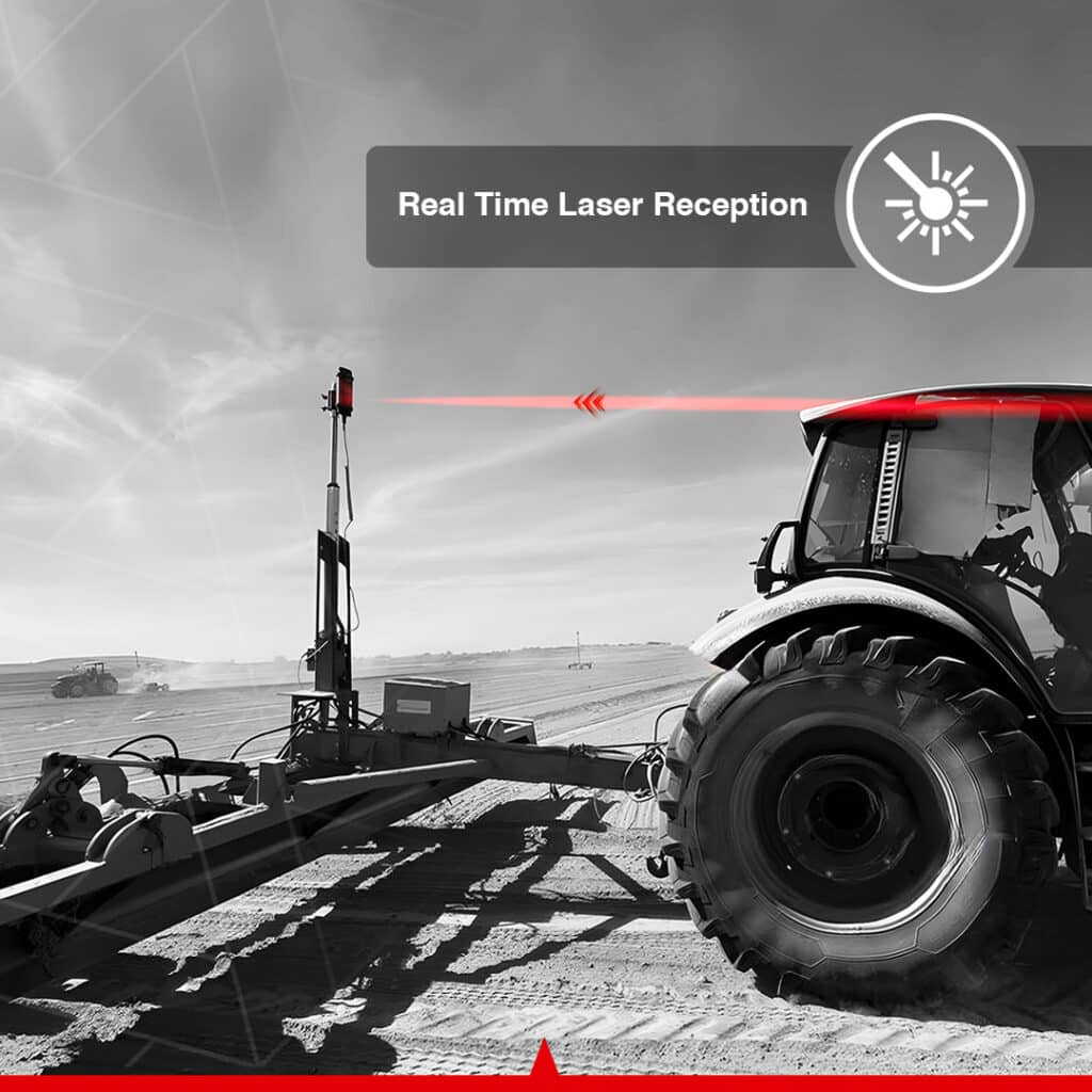
A compatible rotating red-beam laser transmitter establishes the reference plane across the work area. The receiver detects its position relative to that plane and communicates with the control box through the CAN connection. Operators can use visual guidance in Manual mode or let the controller raise and lower the blade through compatible hydraulic solenoid valves in Automatic mode.
The included mast adds controlled receiver-height adjustment from the cab and enables the Gold-CAN Survey workflow when the system is configured for the electric mast. This makes the package suitable for farmers, land-leveling contractors and compatible grading-machine operators who need both blade elevation control and powered receiver positioning. The laser transmitter and machine-specific hydraulic equipment are selected separately.
The package brings receiver positioning, elevation assessment and blade control into the same machine-mounted system.
Survey readings are relative to the chosen reference. The operator remains responsible for the grading plan, machine travel, material movement and verification of the completed surface.
| Included component | Function |
|---|---|
| CP210-CAN control box | Operator interface, grade processing, blade control and mast settings |
| MD205-CAN laser receiver | 360° detection of the rotating laser reference |
| PM400-CAN electric power mast | Powered receiver-height adjustment and Survey mode support |
| MA400 mast shaft | Mechanical shaft assembly of the PM400-CAN |
| MB400 mast control box | Control component of the PM400-CAN assembly |
| PM400-CAN shock mount | Mounting component supplied with the mast |
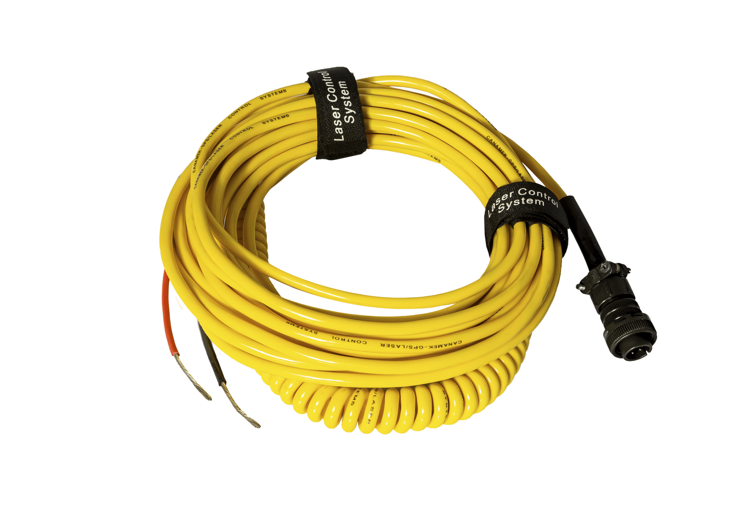
| Power cable | Machine power connection |
| Blade / hydraulic valve cable | Electrical connection to compatible blade-control valves |
| Control-box-to-mast cable | Connection between CP210-CAN and PM400-CAN |
| Mast-to-receiver cable | Connection between PM400-CAN and MD205-CAN |
| Aluminum carry case | Storage and transport of the control-kit components |
The MA400 shaft, MB400 control box and shock mount form the PM400-CAN Power Mast assembly. They are listed separately to identify the mast components supplied with this package.
The standard Gold-CAN Laser Control System provides the same core grade guidance and compatible hydraulic blade-control functions. This bundle adds the PM400-CAN and its connections, allowing the operator to adjust receiver height from the cab and use the electric-mast Survey configuration.
The package retains one MD205-CAN machine receiver. The mast expands receiver positioning and surveying functions; the system remains a single-receiver blade elevation control installation.
A compatible rotating red-beam laser transmitter provides the reference used by the receiver. Level, single-slope and dual-slope operation depend on the selected transmitter’s capabilities and setup. The transmitter and its support tripod are separate equipment.
The installation also requires a compatible grading machine or implement, suitable receiver and mast mounting, and an electrical supply that meets the component requirements. Automatic blade control requires compatible hydraulic solenoid valves and the correct machine interface. A valve assembly, quick-connect block and hydraulic hoses are not listed as included in this control-and-mast bundle.
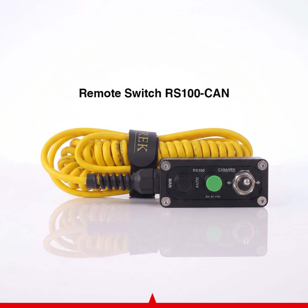
The RS100-CAN wired remote provides blade up/down commands and Manual/Automatic mode selection through the CP210-CAN. It is an optional accessory for operators who want these functions available at an additional control position.
The PM400-CAN moves the laser receiver vertically under control of the CP210-CAN. Its 39.37 in / 1,000 mm stroke provides a defined adjustment range for positioning the receiver relative to the laser reference and grading implement.
A digital measurement system reports mast position in imperial or metric units. The stated position accuracy is ±0.04 in / ±1 mm. This figure applies to the mast’s positioning measurement and should be considered separately from the laser receiver’s selectable grading control bands.
Powered positioning allows the operator to adjust receiver height through the control system instead of manually repositioning the receiver for each change. The steel body, aluminum components and supplied shock mount support integration with field machinery.
Gold-CAN Survey mode uses the PM400-CAN electric mast to evaluate elevations relative to a selected reference point. The same receiver and control box used for grading can assist with identifying high and low areas and evaluating land or road slopes.
The CP210-CAN must be configured for the electric mast to use this workflow. The mast’s digital measurement and selectable units provide the position information used during relative elevation assessment.
This gives operators a way to inspect elevation differences before or during grading with the mounted system. The results support decisions about where surface correction is needed; a suitable grading plan is still required to determine the final surface.
In Automatic mode, the CP210-CAN processes the laser receiver’s grade position and sends commands to compatible on/off hydraulic solenoid valves. The valve installation raises or lowers the blade to keep the receiver within the selected on-grade band.
This control loop combines the laser reference, receiver detection, controller output and machine hydraulics. It can reduce the need for continuous manual blade corrections while the operator manages travel speed, implement loading and soil movement.
The electrical valve cable is part of the connection set. The valve assembly and machine hydraulics must be compatible with the controller’s documented output and the intended blade functions.
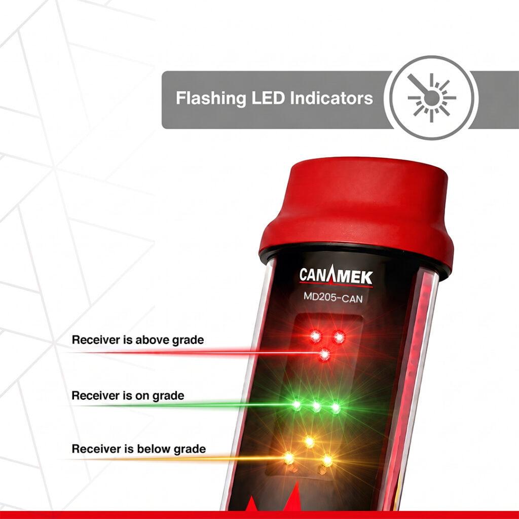
Manual mode displays the receiver’s relationship to the laser plane while the operator controls the hydraulic movement. Above-grade, on-grade and below-grade indicators provide a continuous reference during setup and grading.
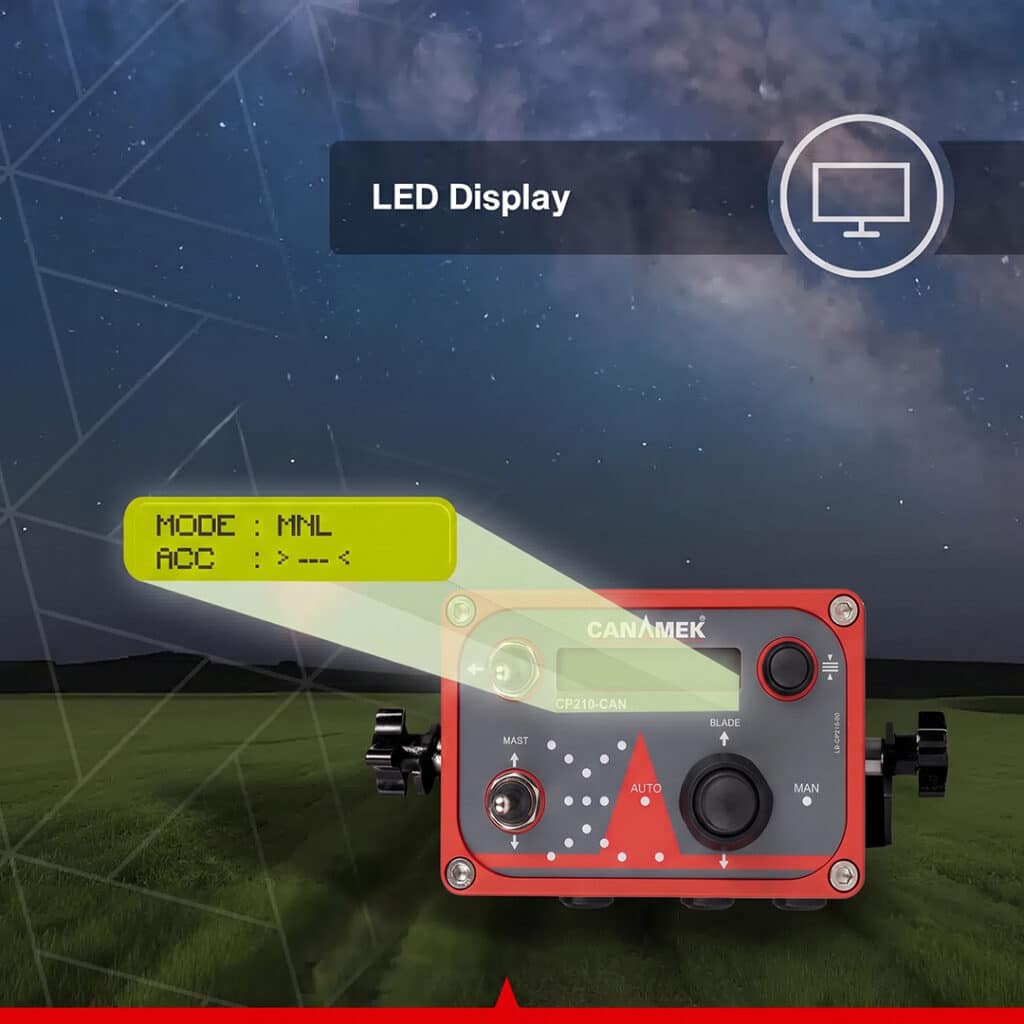
This mode supports work where the operator wants direct control of the implement while retaining laser guidance. The control box shows the selected accuracy, operating mode and blade direction so the operator can monitor the current configuration.
The system provides three control settings:
| Control setting | Tolerance |
|---|---|
| Narrow | ±0.12 in / ±3 mm |
| Intermediate | ±0.35 in / ±9 mm |
| Wide | ±0.55 in / ±14 mm |
A narrower band suits closer grade control where the machine and working conditions can maintain it. Wider settings accommodate applications using a broader control tolerance.
These are system control settings, rather than a guarantee of completed surface accuracy. Actual grading results also depend on the transmitter reference, mounting, hydraulic tuning, travel speed, implement behavior and ground conditions.
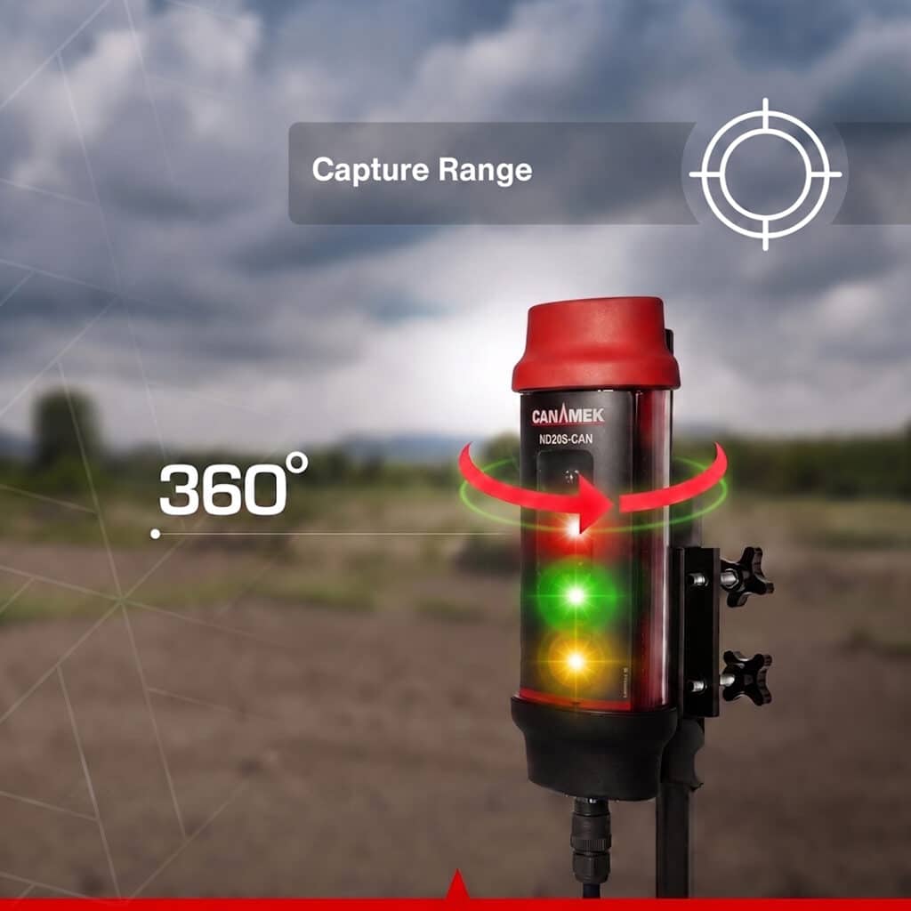
The MD205-CAN receives a compatible rotating red laser around a full 360°. Its 7.48 in / 190 mm measurement window and eight detection positions provide grade information to the controller.
High-visibility flashing LEDs use red for above grade, green for on grade and yellow for below grade. Real-time laser bounce filtration and adjustable signal smoothing help stabilize the information received during machine vibration and movement.
The receiver’s detection angle supports reception as the machine changes direction. A clear optical path between transmitter and receiver remains necessary, because terrain and other objects can block the beam.
The CP210-CAN provides separate hydraulic response settings for blade raising and lowering. Each can be adjusted from 20 to 100 through the menu, covering the manufacturer’s stated 80-step adjustment span.
Separate settings allow the response to be matched to the machine’s lifting and lowering characteristics. Operators and installers can tune these values alongside the selected control band to suit the hydraulic circuit, blade and grading task.
The setting numbers are controller parameters; they are not published hydraulic flow rates or percentages.
Gold-CAN follows the reference plane produced by the external laser transmitter. A suitable transmitter can establish a horizontal plane, a slope along one axis or a plane inclined along two axes.
The receiver and blade-control system then work relative to that plane. The PM400-CAN provides receiver-height adjustment, while the transmitter establishes the plane’s slope.
This allows the package to support different field and grading requirements using an appropriate laser reference. Dual-slope transmitter operation does not provide independent left- and right-side blade control through this single-receiver package.
Visual judgment alone can make repeated grading passes difficult to compare. The rotating laser supplies a common reference, the receiver indicates the machine’s position relative to it, and Automatic mode can apply blade corrections through compatible hydraulics.
The included mast adds controlled receiver positioning when the setup requires a height change. Together, these functions help the operator maintain a consistent elevation reference through survey, setup and grading activities.
High spots, low areas and unsuitable surface slopes can interfere with planned drainage. Survey mode helps assess relative elevation differences, while laser guidance and automatic blade control support grading to the selected reference plane.
Correcting the surface according to a suitable drainage plan can help direct water toward intended outlets. Results depend on soil conditions, drainage infrastructure, weather, surface design and the quality of the grading work.
The receiver communicates with the control system and receives power through the CAN connection. The CP210-CAN also supports the electric mast through its dedicated system connection, with separate connections for machine power, hydraulic valve control and the optional remote switch.
The backlit display presents mode, control setting, blade direction and menu information. Connection monitoring warns when receiver communication is interrupted, and short-circuit protection is included. Flashing grade-position indicators can show the last detected beam position when laser reception is lost.
The user menu provides software version and serial-number information, active and inactive time counters, a configurable Automatic-mode buzzer and a factory reset function. Technical parameters are accessed through a password-protected menu. These functions give operators and support staff useful information when checking settings or troubleshooting the system.
The package supports agricultural field leveling, farm drainage work, scraper control, compatible land-leveler operation, precision earthmoving and finish grading. Its surveying capability also supports relative land and road elevation assessment.
Machine suitability depends on the mounting arrangement and hydraulic interface. The same control principles can be applied to appropriate blade-controlled grading equipment, with installation components selected for the machine and task.
This bundle combines the Gold-CAN grade-control platform with the powered receiver positioning required for its electric-mast Survey workflow. The control box manages the operating settings, the receiver tracks the laser plane, and the mast provides controlled vertical adjustment with digital position measurement.
For farmers: it supports field leveling, relative elevation checks and surface correction based on a suitable grading or drainage plan.
For land-leveling contractors: it provides manual guidance, automatic blade control and receiver-height adjustment within the same machine-mounted system.
For grading and earthmoving operators: selectable control bands and independent hydraulic response settings allow the installation to be configured for compatible machinery and different stages of grading.
For drainage and survey work: the included electric mast enables relative high/low assessment and land or road slope evaluation against a selected laser reference.
It is a laser grade-control package combining a CP210-CAN control box, one MD205-CAN machine receiver and an included PM400-CAN electric mast. It supports Manual grade guidance, Automatic blade raise/lower control through compatible hydraulics and relative elevation surveying with the electric mast.
It adds the PM400-CAN power mast and mast connections to the Gold-CAN control platform. The mast provides powered receiver-height adjustment from the cab and enables the supported Survey workflow when the controller is configured for the electric mast.
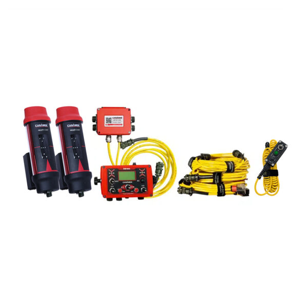
The package includes the CP210-CAN control box, MD205-CAN receiver, PM400-CAN electric mast, system cables and an aluminum carry case for the control kit. The PM400-CAN assembly includes its MA400 shaft, MB400 control box and shock mount.
No. A compatible rotating red-beam laser transmitter is required separately. Its capabilities determine whether the system can follow a level, single-slope or dual-slope reference plane.
They are not listed as included in this control-and-mast bundle. Automatic blade operation requires a compatible hydraulic solenoid valve installation, selected for the machine. The package includes the blade/valve electrical cable.
Yes. The included PM400-CAN raises and lowers the receiver through the CP210-CAN controls. Its digital position measurement provides imperial or metric indication during receiver positioning.
The mast provides a 39.37 in / 1,000 mm stroke. This specification describes its vertical adjustment travel, not the total installed height of the mast and receiver.
No. The PM400-CAN’s stated ±0.04 in / ±1 mm accuracy relates to mast position measurement. Gold-CAN has separate control settings of ±0.12 in / ±3 mm, ±0.35 in / ±9 mm and ±0.55 in / ±14 mm. Finished grading accuracy also depends on the reference laser, installation, hydraulics, machine operation and ground conditions.
Yes. With the included PM400-CAN connected and the electric mast setting enabled, Survey mode supports high/low assessment relative to a selected reference point. It can assist with land and road elevation analysis and slope evaluation.
The MD205-CAN detects its position relative to the rotating laser plane. The CP210-CAN processes that information and commands compatible hydraulic solenoid valves to raise or lower the blade within the selected control band.
Yes. Manual mode provides visual above-grade, on-grade and below-grade information while the operator controls the machine hydraulics. Automatic and Survey modes are also available for their respective workflows.
The selectable settings are ±0.12 in / ±3 mm, ±0.35 in / ±9 mm and ±0.55 in / ±14 mm. Select the setting according to the grading requirement and the machine’s ability to maintain the chosen control band.
The system supports suitable scrapers, land levelers, grading machines and other compatible blade-controlled equipment. Suitability depends on the electrical supply, hydraulic valve interface, mast and receiver mounting, and cable routing. Compatible trenching applications are also documented.
The Gold-CAN system is intended for compatible rotating red-beam laser transmitters. A clear optical path to the receiver is required. The transmitter’s working range and slope functions must suit the intended project.
Yes, when the external transmitter supports and is configured for the required slope. Gold-CAN follows the resulting laser plane, while the PM400-CAN adjusts receiver height. The mast itself does not set the transmitter’s slope.
No. This package uses one MD205-CAN receiver for blade elevation control. Dual-slope capability refers to the external laser plane and does not add independent left- and right-side blade control.
Yes. The CP210-CAN provides independent raise and lower response settings from 20 to 100. These controller parameters allow the hydraulic response to be tuned to the machine; they are not specified flow rates or percentages.
The CP210-CAN control box and MD205-CAN receiver each support 12–24 V DC, while the PM400-CAN mast supports 10–24 V DC. The documented valve control output is 12 V DC. The machine supply and solenoid valve interface must be checked against these separate requirements.
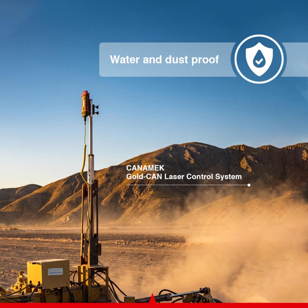
The CP210-CAN control box is rated IP66 and the MD205-CAN receiver is rated IP68. The system cables use water- and dust-resistant connectors. These component ratings should not be treated as a single rating for the entire assembled installation.
The power cable is 13.12 ft / 4 m, and the blade/valve cable is 24.77 ft / 7.55 m. The control-box-to-mast cable is 27.89 ft / 8.5 m, and the mast-to-receiver coil cable has a published length range of 8.2–18.0 ft / 2.5–5.5 m.
Yes. The PM400-CAN component list includes the shock mount together with the MA400 shaft and MB400 mast control box. CANAMEK recommends shock mounting for high-vibration applications.
Yes. The optional RS100-CAN wired remote connects to the CP210-CAN and provides blade up/down commands and Manual/Automatic mode selection. It is supplied separately from this bundle.
No GNSS base station is required for the documented laser-control workflow. The system uses a compatible rotating red-beam laser transmitter as its elevation reference.
The system includes a 2-year warranty and CANAMEK after-sales support seven days a week.
| Specification | Details |
|---|---|
| Product | CANAMEK-Gold-CAN Laser Land Leveling Control System with Power Mast |
| Product SKU | CNMK-LLL-1004 |
| System category | Laser machine control with electric receiver mast |
| Control box | CP210-CAN |
| Machine receiver | One MD205-CAN |
| Included electric mast | One PM400-CAN |
| Mast assembly components | MA400 shaft, MB400 control box and shock mount |
| Operating modes | Manual, Automatic and Survey |
| Survey configuration | Included PM400-CAN connected and electric mast setting enabled |
| Laser reference | Compatible rotating red-beam transmitter, supplied separately |
| Supported reference planes | Level, single slope or dual slope, according to transmitter capability |
| Grade-control settings | ±0.12 in / ±3 mm; ±0.35 in / ±9 mm; ±0.55 in / ±14 mm |
| Automatic blade functions | Raise and lower through compatible hydraulic solenoid valves |
| Manual operation | Visual grade guidance with operator-controlled hydraulics |
| System communication | CAN bus |
| Supported applications | Land leveling, field grading, farm drainage, precision earthmoving, finish grading, compatible trenching and relative elevation surveying |
| Included connections | Machine power, blade/valve cable, control-box-to-mast cable and mast-to-receiver cable |
| Carrying equipment | Aluminum carry case for the control kit |
| Manufacture | Canada |
| Warranty | 2 years |
| After-sales support | 7 days a week |
| Specification | Details |
|---|---|
| Type | Microprocessor-based CAN machine control panel |
| Supply voltage | 12–24 V DC |
| Ingress protection | IP66 |
| Operating modes | Manual, Automatic and Survey |
| Control settings | ±0.12 in / ±3 mm; ±0.35 in / ±9 mm; ±0.55 in / ±14 mm |
| Display | Backlit system information display |
| Displayed operating information | Current mode, selected accuracy, blade direction and menu data |
| Grade display | LED grade-position indicator |
| Blade commands | Raise and lower |
| Automatic output | Compatible hydraulic solenoid valve control |
| Documented valve output voltage | 12 V DC |
| Raise response setting | Independently adjustable from 20 to 100 |
| Lower response setting | Independently adjustable from 20 to 100 |
| Response adjustment span | Manufacturer-stated 80-step range |
| Mast configuration settings | No Mast, Electric Mast or Hydraulic Mast |
| Mast supplied in this package | PM400-CAN electric mast |
| Mast controls | Raise and lower |
| Mast measurement units | Millimeters and inches |
| Signal configuration | Adjustable laser smoothing |
| Receiver connection monitoring | Receiver/control-box communication error indication |
| Electrical protection | Short-circuit protection |
| Automatic-mode buzzer | User-selectable On/Off |
| Receiver / mast connection | Dedicated CAN receiver/electric mast connector |
| Hydraulic connection | Dedicated valve cable connector |
| Power connection | Dedicated machine power connector |
| Remote connection | Dedicated connection for optional RS100-CAN |
| User setup functions | Valve response, mast type, buzzer, measurement units and laser smoothing |
| Reset function | User-accessible factory reset |
| Technical menu | Password-protected parameter access |
| Identification information | Software version and serial number accessible through the menu |
| Time counters | Active and inactive system time |
| Specification | Details |
|---|---|
| Type | 360° CAN laser machine receiver |
| Quantity | One |
| Compatible reference | Rotating red-beam laser |
| Housing | Aluminum alloy |
| Ingress protection | IP68 |
| Capture angle | 360° |
| Measurement window | 7.48 in / 190 mm |
| Detection positions | Eight distinct beam positions |
| Selectable control settings | ±0.12 in / ±3 mm; ±0.35 in / ±9 mm; ±0.55 in / ±14 mm |
| Above-grade indication | Red LEDs |
| On-grade indication | Green LEDs |
| Below-grade indication | Yellow LEDs |
| Indicator type | High-visibility flashing LEDs |
| Weight | 6.28 lb / 2.85 kg |
| Supply voltage | 12–24 V DC |
| Power supply connection | Through CAN connection |
| Communication | CAN bus |
| Receiver interface | Combined CAN data and power connection |
| Signal processing | Real-time laser bounce filtration |
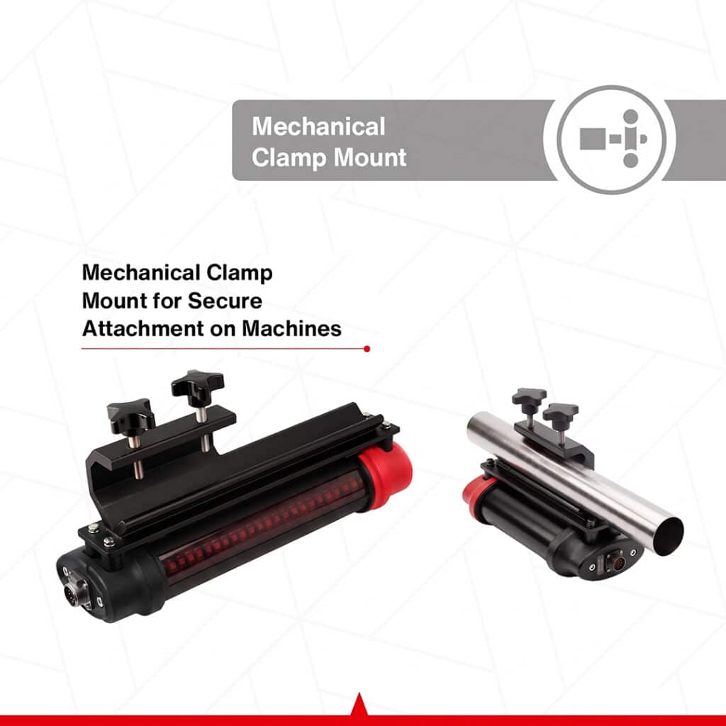
| Mounting | Mechanical clamp |
| Application | Manual guidance and automatic machine grade control |
| Specification | Details |
|---|---|
| Package status | Included |
| Quantity | One |
| Function | Powered receiver-height adjustment and relative elevation Survey mode support |
| Shaft assembly | MA400 |
| Mast control box | MB400 |
| Shock mount | Included with the PM400-CAN assembly |
| Construction | Steel body with aluminum components |
| Measurement system | Digital position measurement |
| Supply voltage | 10–24 V DC |
| Vertical stroke | 39.37 in / 1,000 mm |
| Stated position accuracy | ±0.04 in / ±1 mm |
| Measurement units | Imperial and metric; inches and millimeters |
| Control method | Raise/lower control from CP210-CAN |
| Receiver interface | Integrated receiver mounting interface |
| System integration | CAN-based |
| Survey mode | Supported with the electric mast configuration |
| Mounting guidance | Shock mount recommended for high-vibration applications |
The stroke describes available mast travel, not total installed height. Mast position accuracy is separate from the grading control tolerance and finished-surface accuracy.
| Connection / property | Specification | Function / details |
|---|---|---|
| Machine power cable | 13.12 ft / 4 m | Machine battery to CP210-CAN |
| Blade / hydraulic valve cable | 24.77 ft / 7.55 m | CP210-CAN to compatible valve assembly |
| Control-box-to-power-mast data cable | 27.89 ft / 8.5 m | CP210-CAN to PM400-CAN |
| Power-mast-to-receiver coil data cable | 8.2–18.0 ft / 2.5–5.5 m | PM400-CAN to MD205-CAN |
| Cable jackets | Oil-resistant | Mobile machinery construction |
| Mechanical suitability | High mechanical stress resistance | Machine vibration and movement |
| Temperature suitability | Low-temperature cable construction | Field use |
| Connector type | Circular MIL-style connectors | Dedicated machine-system connections |
| Connector environmental design | Water- and dust-resistant | Field installation |
| Connector arrangement | Application-specific keyed connections | Helps prevent incorrect connections |
| Specification | Details |
|---|---|
| Supported valve type | Compatible on/off solenoid valves |
| Documented valve output | 12 V DC |
| Controlled blade movements | Raise and lower |
| Automatic control basis | Laser receiver position relative to the reference plane |
| Raise/lower tuning | Independent controller settings |
| Response setting range | 20–100 |
| Hydraulic mast configuration support | Available in controller settings; this package supplies the PM400-CAN electric mast |
| Compatible equipment | Suitable scrapers, land levelers, grading machinery and other compatible blade-controlled equipment |
| Installation requirements | Correct electrical supply, hydraulic interface, mast/receiver mounting and cable routing |
| Hydraulic valve assembly | Separate machine-specific equipment |
| Quick-connect block and hydraulic hoses | Not listed as included in this bundle |
The controller's input voltage and valve output voltage describe different parts of the installation. The solenoid valve and machine interface must match the documented control output.
| Specification | Details |
|---|---|
| Published Gold-CAN operating temperature | −4°F to 140°F / −20°C to 60°C |
| CP210-CAN ingress protection | IP66 |
| MD205-CAN ingress protection | IP68 |
| Receiver communication warning | Displayed when receiver/control-box communication is interrupted |
| Lost-laser indication | Flashing grade-position indication |
| Last beam position | Last detected position can be shown visually |
| Blade direction | Displayed on CP210-CAN |
| Current control setting | Displayed on CP210-CAN |
| Operating mode | Displayed on CP210-CAN |
| Automatic-mode sound | Configurable internal buzzer |
| Electrical fault protection | Short-circuit protection |
The component IP ratings above apply to the control box and receiver individually.
| Specification | Details |
|---|---|
| Package status | Optional; supplied separately |
| Type | Wired machine-control remote switch |
| Housing | Aluminum |
| Blade commands | Up / Down |
| Mode commands | Automatic / Manual |
| Switch construction | Heavy-duty |
| Environmental design | Water- and dust-resistant switches |
| Cable | Coiled cable with high mechanical resistance |
| Connection | Dedicated CP210-CAN remote connector |
Use laser guidance or compatible automatic blade control to grade fields against a consistent reference plane. The included mast allows receiver-height adjustment from the cab during setup.
Use Survey mode and the PM400-CAN to assess high and low locations relative to a selected reference point before planning or carrying out surface correction.
Evaluate relative elevations and grade toward a planned drainage reference. With a suitable slope-capable transmitter, the system supports surface shaping toward intended outlets.
Control blade elevation on compatible scrapers and land levelers. Operators can select Manual guidance or Automatic corrections and tune hydraulic response to the equipment.
Maintain a laser elevation reference during soil redistribution. Adjustable control tolerances and blade response support different stages of the earthmoving work.
Use the selected control band to guide final surface grading with compatible blade-controlled equipment. Powered receiver positioning supports setting the working elevation reference.
Follow a level, single-slope or dual-slope laser plane according to the external transmitter's capabilities and the project requirements.
Use the electric-mast Survey configuration to evaluate relative elevations and support land or road slope checks before or during grading.
Provide laser elevation guidance for compatible trenching machinery where the receiver, mast and machine interface can be correctly installed for the task.
Be the first to review this product.
Every unit ships with everything needed to put it to work in under an hour.
Get sizing help and tech answers from a real human, in <2 min.
Call +1 (855) CANAMEKTell us your acreage and crop, get a turnkey estimate in 24 hours.
Email sales →

Write a review